
Initial Setup & Line-Following
Setup
We needed to set up our BeagleBone Black and test measuring inputs and setting up the PWM. To do this, we decided to create a line-following robot that used infrared to find and follow the line. We setup the BeagleBone and used a JS library called BlackLib to read from the analog pins and to use the PWM to power the motors for the wheels.
Line-Following
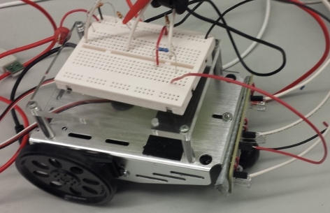
For the line-following circuit we used three IR emitters and three IR transistors. The circuit operats by emitting IR, which is then either reflected back by the white floor, or absorbed by the black line. The transistors are then either in saturation and result in a smaller voltage drop or they are in the triode region and there is a larger voltage drop. Based on the voltages after the transistors, we could determine which transistors were over the line and we could use the analog input pins to then direct the robot as needed. The circuit can be seen in the pictures below.

Turning
We wanted to be able to command our robot to drive in a given direction as a result of line sensor input, thus implementing a closed loop system. Since the Boe-Bot’s drivetrain consists of two coaxial motors and one caster wheel, we needed a set of formulae that matched this specification. After a quick search online yielded no results, it was time to hit the white board.
In essence, we needed to determine the speed of each wheel as a function of the robot’s velocity at the midpoint of the two wheels, which we denote as \(v_f\) and the direction, which we denote as \(x \in [-1,1]\). Here, \(x=-1\) means a hard left with the left wheel is stationary, \(x=0\) means driving straight, and \(x=1\) means a hard right with the right wheel is stationary. This continuous range of values makes it easier for us to adjust direction based upon inputs.
We were able to determine values for the left wheel velocity, \(v_l\), and the right wheel velocity, \(v_r\), by solving for the axis of rotation, \(r\). We defined \(r\) to the distance between the axis of rotation and the axle’s midpoint along the axle line, so that \(+r\) is to the right and \(-r\) is to the left. We found the radius to be \[|r|=\frac{d_w}{2|x|}\] where \(d_w\) is the distance between the wheels and \(r\) has the same sign as \(x\). We then define angular velocity to be \(\omega = v_f / r\). Finally, we can express: \[v_l=\omega (r - \frac{1}{2}d_w)\] \[v_r=\omega (r + \frac{1}{2}d_w)\]
These equations are easily integrated into our code and give us precise control over the motion of our vehicle.
Demo
The video below shows the finished line-following robot on a small track.